

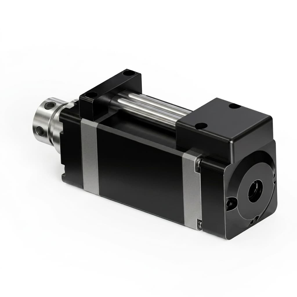
BLDC vs. Coreless Motors in Micro Actuators: An Integration Guide
A technical breakdown of when to pair your embedded GaN servo drive with a traditional BLDC motor versus a coreless DC motor for compact robotics.
Engineers designing micro actuators for humanoid robots or surgical tools face a hard choice: traditional Brushless DC (BLDC) motors or Coreless (Ironless) DC motors.
Executive Summary (TL;DR)
- Coreless motors offer zero cogging torque and blisteringly fast acceleration, perfect for haptics.
- Traditional BLDC motors provide superior thermal mass for high-continuous-torque joints.
- Driving a low-inductance coreless motor requires high-frequency (>100kHz) GaN inverters to prevent stator burnout.
Their physical characteristics demand entirely different drive electronics. Here is a breakdown of the topology trade-offs, and why wide-bandgap GaN inverters have changed the rules for coreless integration.
Topology Comparison Matrix
Before diving into the physics, here is a high-level buyer's comparison of the two topologies when scaled down to micro-actuator sizes (e.g., < 40mm diameter).
| Characteristic | Traditional Slotted BLDC | Coreless (Ironless) DC/BLDC |
|---|---|---|
| Cogging Torque (Ripple) | Noticeable (Requires FOC mitigation) | Zero (Perfectly smooth) |
| Rotor Inertia | Moderate to High | Ultra-Low (Blistering acceleration) |
| Thermal Mass (Overload limit) | High (Absorbs heat spikes well) | Low (Burns out quickly if stalled) |
| Phase Inductance | High (mH range) | Ultra-Low (µH range) |
| Best Application Fit | High continuous torque (Arms, Legs) | High dynamics / Haptics (Fingers, Surgical) |
Traditional BLDC Motors
Traditional slotted BLDC motors utilize a stator with iron laminations and copper windings.
Advantages:
- High Torque Density: The iron core allows for strong magnetic flux paths, delivering excellent continuous and peak torque relative to their volume.
- Thermal Durability: The iron stator provides significant thermal mass, allowing the motor to absorb heat spikes during peak loads without instantly destroying the windings. This is critical for applications like robotic legs where sudden impacts generate massive back-EMF and current spikes.
Integration Challenges:
- Cogging Torque: The interaction between the permanent magnets on the rotor and the stator teeth creates cogging. Advanced Field Oriented Control (FOC) algorithms and high-resolution absolute encoders are required to mitigate this for smooth low-speed operation.
Coreless (Ironless) Motors
Coreless motors feature a self-supporting winding basket without an iron core, spinning around a stationary central magnet (or vice versa).
Advantages:
- Zero Cogging: Without an iron core, there is no magnetic detent. This allows for incredibly smooth, precise positioning and zero torque ripple, ideal for haptic feedback controllers or surgical instruments.
- Ultra-Low Inertia: The lightweight rotor allows for blistering acceleration and deceleration rates, crucial for highly dynamic mechanisms like humanoid fingers or high-speed pick-and-place heads.
Integration Challenges:
- Poor Thermal Mass: The copper windings have very little thermal mass. A stall condition or current spike can burn out a coreless motor almost instantly. Driving them requires highly responsive current limiting in your servo drive.
The Crucial Role of the Servo Drive (The Low Inductance Problem)
The most significant integration challenge with coreless motors is their inherently low phase inductance—often in the low microhenry ($\mu H$) range.
When driven by a standard silicon-based PWM servo controller (typically switching at 20 kHz to 40 kHz), this low inductance results in massive current ripple during the PWM switching cycle.
The Physics of Current Ripple
The current ripple (delta I) in a motor phase is inversely proportional to the switching frequency (f_sw) and the inductance (L):
Delta I ≈ V_bus / (L * f_sw)
With a tiny L, the ripple becomes huge. This ripple doesn't produce torque; it only produces I^2*R heating in the windings, destroying the motor efficiency and risking premature burnout.
The GaN Solution
This is where Gallium Nitride (GaN) shines. By utilizing GaN power stages, our micro servo drives can switch at significantly higher frequencies (e.g., 100 kHz to 200 kHz) without suffering from the prohibitive switching losses that would melt a silicon MOSFET.
By increasing f_sw by a factor of 5x, we linearly decrease the current ripple by 5x. This allows you to drive ultra-low inductance coreless motors smoothly and efficiently, without the need to add bulky, heavy external inductor chokes in series with the motor phases.
Final Verdict
Don't kill a high-end coreless motor with a low-frequency silicon drive. If you need extreme dynamics, pair it with a >100 kHz GaN PCBA to keep the stator alive.
More Posts
Thermal Management Strategies for Micro GaN Servo Drives in Robotic Joints
Actionable stack-up and firmware strategies for managing heat dissipation in ultra-compact GaN-based servo PCBA stacks for humanoid robots and cobots.

GaN vs. Silicon Servo Drives in Mobile Robotics: A Procurement Cost-Benefit Analysis
Compare GaN vs. silicon servo drives for mobile robots. Review TCO, battery, thermal, payload, supplier checks, and request a GAN Servo evaluation kit.
48V GaN Servo Architecture for Humanoid and AMR Procurement
See why 48V GaN servo drives help humanoid and AMR teams cut harness weight, manage heat, vet suppliers, and request a 48V evaluation kit for pilot sourcing.