LogoLogoGaN Servo
Start inquiry
LogoLogoGaN Servo
WhatsApp
LogoLogoGaN Servo

Micro GaN servo PCBA and robotic joint servo OEM manufacturing from prototype to mass production.

Inquiry Email

[email protected]

Email app

Include target torque/speed, quantity, and delivery location.

Instant Chat

+8618857971991

Chat on WhatsApp

Direct response from our engineering team.

Products
  • Micro GaN Servo PCBA
  • Robotic Joint Servo OEM
  • Low Voltage GaN Module
  • Driver-Encoder Stack
  • 48 V Bare-Board Driver
  • Ring-Shaped Joint PCBA
  • Micro GaN Surgical Drive
  • High-Frequency UAV GaN ESC
Solutions
  • Humanoid Micro Actuators
  • Drone and eVTOL Servo Control
  • Medical Robotic Arms
  • Precision Grippers
OEM Capabilities
  • OEM Manufacturing
  • SMT PCBA Assembly
  • Firmware and Control Loop
  • Robot Joint BOM Turnkey
  • Prototype to Mass Production
Resources
  • Blog
  • About
  • Contact / RFQ
  • Quality Facilities
  • STEP Envelope Guide
  • Privacy Policy
  • Cookie Policy
  • Terms of Service
© 2026 GaN Servo. All Rights Reserved.|Backed by Linkup Ai Co., Ltd. Manufacturing delivered by the Advanced Manufacturing Division of Linkup Precision.
← Back to ProductsUAV GaN Drive Electronics

Reduce drive weight without turning EMI, heat, and vibration into flight-program risk

A high-frequency GaN ESC and servo-control electronics path for UAV payload actuation, gimbals, compact autonomous platforms, and eVTOL-adjacent actuator programs where weight, sensor stability, thermal condition, and repeatability matter together.

Target Buyer:For UAV and robotics OEMs that need lighter custom drive electronics than a catalog industrial module can offer.
Request UAV drive reviewRequest integration guide
High-frequency GaN ESC and motor-drive electronics for UAV programs
Buyer Problem

A lighter drive is not enough if it destabilizes the aircraft system

UAV programs evaluate electronics as part of a tightly coupled airframe, sensor, radio, and thermal environment. The page focuses the buyer discussion on the risk controls that make a lightweight GaN drive quoteable.

High-frequency switching can disturb nearby systems

Navigation sensors, radios, encoders, and harnesses can be affected if grounding, filtering, cable route, and load conditions are not reviewed.

Thermal data changes with airflow and enclosure

Bench thermal results mean little unless voltage, current, duty cycle, mounting, airflow, and enclosure condition are recorded.

Pilot fleets expose connector and vibration issues

A board that works on a bench can still fail through connector retention, solder stress, or uncontrolled firmware/test revisions.
Qualification Snapshot

Fast buyer fit check

Use cases
Payload actuation, gimbal, compact drive, UAV servo
Format
Bare PCBA or compact lightweight module
Primary risks
EMI, sensor/radio stability, vibration, thermal data
Best stage
Prototype, pilot fleet, weight-driven redesign
Solution Overview

Turn High-Frequency UAV GaN ESC from a possible board into a quoteable OEM subsystem

Each value prop below is paired with the evidence a serious buyer should scope before prototype, pilot, or repeat production.

Weight-sensitive electronics planning

Board outline, copper, connector, enclosure, and heat path are reviewed against the UAV weight target and endurance tradeoff.

Evidence to scope: Scope board mass target, outline, mounting, connector retention, and heat-path assumptions.

EMI and sensor stability review

Switching behavior, grounding, filtering, radio/sensor proximity, and cable routing are treated as pilot risks from the beginning.

Evidence to scope: Ask for load-test notes and sensor or bus stability checks under realistic operating conditions.

Thermal evidence under stated airflow

Thermal evaluation is framed by current profile, duty cycle, enclosure, airflow, and mounting condition so claims can be compared fairly.

Evidence to scope: Include airflow or enclosure assumption, duty cycle, altitude if relevant, and thermal acceptance method.

Pilot fleet release control

Firmware revision, fixture checks, labels, packaging, and outgoing records help keep multiple prototype aircraft consistent.

Evidence to scope: Request pilot fleet serial tracking, firmware lock, and functional test package.

Product Visuals

Relevant board and actuator references

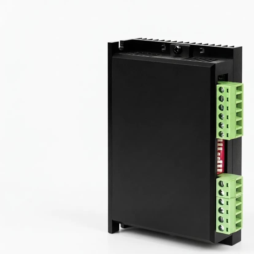
Lightweight high power density drive board for aerial robotics
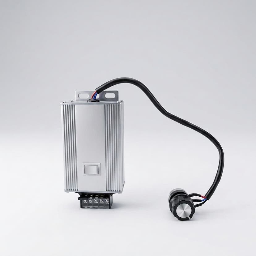
Compact BLDC inverter board for drone payload actuation
Engineering Context

Proof assets buyers should ask to review

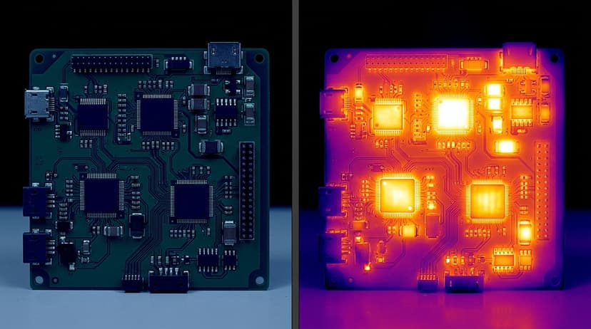
Thermal review reference for lightweight UAV drive electronics
Inspection and test reference for pilot fleet electronics release
Decision Matrix

Questions that decide whether this product should move to RFQ

Buyer questionEngineering answerEvidence to scope
Is this only a propeller ESC?No. It covers UAV drive electronics for payload actuation, gimbals, compact BLDC/PMSM drive, and servo-control modules.Application context, motor data, control mode, mechanical envelope
How should EMI risk be reviewed?Document sensor/radio proximity, grounding, filtering, harness route, and load-test method before pilot release.EMI concern list, cable map, operating-load validation plan
Can weight and thermal goals be balanced?Yes, if target mass, copper/heat path, airflow, enclosure, and current profile are compared together.Weight target, thermal note, current profile, enclosure condition
What makes the pilot fleet repeatable?Firmware revision, fixture checks, connector retention, labels, and batch records should be part of the release package.Firmware lock, EOL checklist, serial tracking, packaging note
How It Works

From first files to a pilot-ready release package

Step 01

Flight-context intake

Collect use case, motor data, voltage/current, target mass, sensor/radio proximity, airflow, and enclosure assumptions.

Output: UAV integration baseline

Step 02

Board and EMI review

Review switching path, grounding, filtering, connector retention, cable route, and inspection access.

Output: Prototype design-control note

Step 03

Load and thermal validation

Run functional checks, load behavior, thermal sample review, and communication or sensor stability checks.

Output: Prototype validation pack

Step 04

Pilot fleet release

Lock firmware, inspection, labels, packaging, batch records, and outgoing test results for repeatable pilot units.

Output: Pilot fleet release package

Evidence Package

Proof to scope before purchase orders

Integration risk note

Sensor/radio proximity, cable route, grounding, and operating-load concerns.

Thermal condition record

Voltage, current, duty cycle, airflow, mounting, and enclosure assumption.

Vibration and connector checklist

Retention method, harness strain relief, solder stress points, and packaging plan.

Pilot fleet test record

Firmware revision, serial tracking, functional checks, and outgoing acceptance notes.

Fit Check

When this page is the right path

Best for

  • UAV and aerial robotics teams redesigning around weight, heat, and EMI constraints
  • Payload actuation, gimbal, compact autonomous platform, and eVTOL-adjacent drive programs
  • Pilot fleet builds that need consistent firmware, test records, and traceability

Not for

  • Buyers looking only for a low-cost hobby ESC with no documentation package
  • Projects that cannot share current profile, airflow, enclosure, or sensor proximity assumptions

Applications this page should qualify

  • UAV gimbals and payload actuation
  • Drone servo-control modules
  • Lightweight BLDC and PMSM drive electronics for autonomous platforms

RFQ inputs that make the first answer useful

  1. Voltage range, current profile, motor data, control mode, and operating altitude or airflow assumptions
  2. Weight target, board outline, connector retention, vibration condition, and enclosure method
  3. Sensor/radio proximity, EMI concerns, communication protocol, and test command set
  4. Prototype quantity, pilot fleet quantity, EAU, and documentation requirements

Risk Controls

  • High-frequency switching harms sensor or radio stability: Plan grounding, filtering, shielding, cable routing, and operating-load validation before pilot fleet release.
  • Thermal data is measured without real airflow or enclosure conditions: Record voltage, current, duty cycle, airflow, enclosure, and mounting condition with any thermal claim.
Next Step

Have a UAV drive target that is failing on weight or EMI?

Send motor data, voltage/current profile, board outline, weight target, enclosure/airflow assumptions, sensor proximity, and pilot fleet quantity. The first review should identify whether the risk is layout, thermal path, connector retention, or validation scope.

Request UAV drive reviewRequest integration guide

Buyer FAQ

Is this only for propeller ESC programs?

No. The page covers UAV drive electronics and servo-control boards for payload actuation, gimbals, and compact autonomous platforms.

Can you support custom lightweight board shapes?

Yes. Weight target, outline, connector, thermal path, and inspection access should be reviewed before the first build.

Related Resources

  • Drone and eVTOL Servo Control
  • STEP Envelope and Integration Guide
  • Contact / RFQ

Inquiry Email

[email protected]

Email app

Include target torque/speed, quantity, and delivery location.

Instant Chat

+8618857971991

Chat on WhatsApp

Direct response from our engineering team.