LogoLogoGaN Servo
Start inquiry
LogoLogoGaN Servo
WhatsApp
LogoLogoGaN Servo

Micro GaN servo PCBA and robotic joint servo OEM manufacturing from prototype to mass production.

Inquiry Email

[email protected]

Email app

Include target torque/speed, quantity, and delivery location.

Instant Chat

+8618857971991

Chat on WhatsApp

Direct response from our engineering team.

Products
  • Micro GaN Servo PCBA
  • Robotic Joint Servo OEM
  • Low Voltage GaN Module
  • Driver-Encoder Stack
  • 48 V Bare-Board Driver
  • Ring-Shaped Joint PCBA
  • Micro GaN Surgical Drive
  • High-Frequency UAV GaN ESC
Solutions
  • Humanoid Micro Actuators
  • Drone and eVTOL Servo Control
  • Medical Robotic Arms
  • Precision Grippers
OEM Capabilities
  • OEM Manufacturing
  • SMT PCBA Assembly
  • Firmware and Control Loop
  • Robot Joint BOM Turnkey
  • Prototype to Mass Production
Resources
  • Blog
  • About
  • Contact / RFQ
  • Quality Facilities
  • STEP Envelope Guide
  • Privacy Policy
  • Cookie Policy
  • Terms of Service
© 2026 GaN Servo. All Rights Reserved.|Backed by Linkup Ai Co., Ltd. Manufacturing delivered by the Advanced Manufacturing Division of Linkup Precision.
← Back to ProductsHumanoid Joint Electronics

Fit servo electronics around the joint geometry before the mechanical design traps you

A focused path for annular, crescent, or segmented servo PCBA programs where hollow shafts, reducers, through-hole wiring, encoder placement, and repeated joint variants decide whether the actuator architecture can scale.

Target Buyer:For humanoid teams whose mechanical joint architecture is fixed and whose electronics must be shaped around it.
Plan joint electronicsReview turnkey BOM path
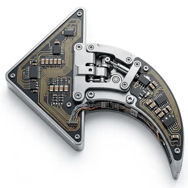
Humanoid joint actuator electronics for constrained ring-shaped packaging
Buyer Problem

Hollow-shaft joints run out of shape before they run out of watts

A humanoid joint electronics program is not only a motor-control problem. It is a packaging, assembly, variant, and traceability problem repeated across many axes of the same robot.

The board shape is constrained by the reducer and shaft

Inner diameter, outer diameter, screw arcs, cable windows, and encoder geometry define the electronics before component selection starts.

One robot creates many nearly identical variants

Without variant governance, fingers, wrists, elbows, and ankles split into uncontrolled BOMs and duplicated validation work.

Assembly access is often ignored too late

Inspection, solder access, connector retention, potting, and rework limits need to be understood before pilot build.
Qualification Snapshot

Fast buyer fit check

Form factor
Ring, crescent, segmented, or stacked PCBA
Joint targets
Wrist, elbow, shoulder, ankle, finger, gripper
Primary risks
Wiring path, heat path, encoder placement, variants
Best stage
Architecture review before CAD freeze
Solution Overview

Turn Ring-Shaped Humanoid Joint PCBA from a possible board into a quoteable OEM subsystem

Each value prop below is paired with the evidence a serious buyer should scope before prototype, pilot, or repeat production.

Board outline tied to joint CAD

The PCBA concept is reviewed against shaft path, reducer stack, mounting arcs, connector direction, and wiring keep-outs.

Evidence to scope: Scope STEP envelope, section drawings, mounting datum, and connector orientation before DFM lock.

Shared electrical core across joint variants

A common control architecture can be adapted by current stage, outline, connector, and harness field instead of restarting every joint.

Evidence to scope: Ask for common-core fields, controlled variant fields, and no-substitution parts in the BOM plan.

Encoder and communication risks handled together

Feedback sensing, bus wiring, grounding, and switching behavior are reviewed as one joint-level integration problem.

Evidence to scope: Include encoder type, bus protocol, cable path, and expected calibration method in RFQ.

Pilot release built around traceability

Serial labels, firmware revision, calibration data, inspection records, and packaging notes prepare the joint electronics for repeated builds.

Evidence to scope: Request a sample release checklist and pilot build record package.

Product Visuals

Relevant board and actuator references

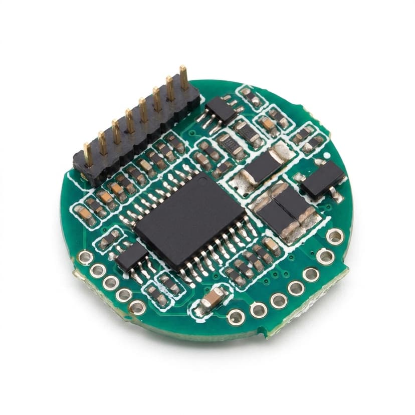
Integrated servo joint electronics for hollow-shaft robotic actuators
Compact humanoid joint module electronics for repeated actuator variants
Engineering Context

Proof assets buyers should ask to review

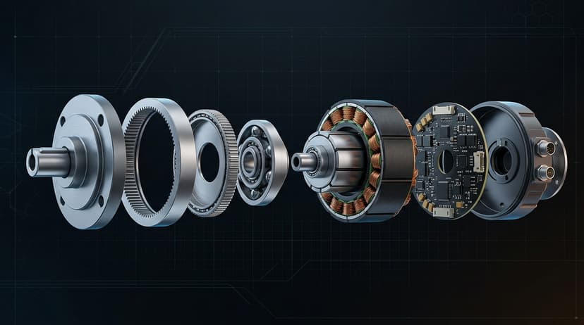
Exploded CAD reference for humanoid joint envelope planning
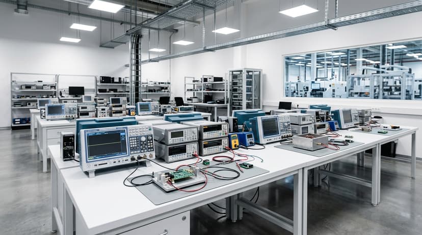
Quality review environment for compact joint electronics
Decision Matrix

Questions that decide whether this product should move to RFQ

Buyer questionEngineering answerEvidence to scope
Can the board follow a non-rectangular joint shape?Yes, when outline, panelization, tooling, inspection access, and assembly sequence are reviewed before quotation.DXF/STEP outline, panelization note, inspection access map
How do we keep many joint variants controlled?Define a shared core architecture and only allow controlled changes for outline, current stage, connector, and firmware parameters.Variant matrix, BOM fields, firmware revision plan
Will wiring and encoder placement survive vibration?Review connector retention, cable route, sensor placement, grounding, and functional test under realistic load.Connector spec, encoder note, vibration or retention requirement
Can this become a turnkey joint electronics package?Drive PCBA, encoder interface, harness, firmware handoff, labels, packaging, and release records can be coordinated as one program.BOM scope, CTQ list, FAI needs, packaging and traceability notes
How It Works

From first files to a pilot-ready release package

Step 01

Joint envelope intake

Collect CAD, shaft path, reducer stack, motor data, connector keep-outs, and joint variant list.

Output: Mechanical-electrical boundary map

Step 02

Common-core planning

Separate shared control architecture from joint-specific power, outline, connector, and calibration differences.

Output: Variant governance table

Step 03

Pilot build validation

Confirm fit, inspection access, signal integrity, firmware revision, calibration, and functional test coverage.

Output: Pilot evidence and issue log

Step 04

Repeat-order release

Lock approved BOM, serial traceability, packaging, labels, and controlled engineering-change flow.

Output: Joint electronics release package

Evidence Package

Proof to scope before purchase orders

Envelope review note

Ring/crescent outline, shaft clearance, connector path, and mounting datum.

Variant matrix

Common architecture fields and joint-specific changes for each actuator family.

Pilot inspection plan

AOI or microscope access, connector retention, polarity checks, and rework constraints.

Traceability package

Serial label, firmware revision, calibration method, and outgoing release record.

Fit Check

When this page is the right path

Best for

  • Humanoid actuator teams with hollow-shaft or pancake joint constraints
  • Programs that need repeated but controlled joint electronics variants
  • OEMs that want PCBA, encoder interface, harness, and release evidence coordinated together

Not for

  • Buyers looking for a stock finished humanoid joint with fixed public dimensions
  • Projects that cannot provide CAD envelope, joint variant list, or motor/encoder data

Applications this page should qualify

  • Humanoid wrists, elbows, shoulders, ankles, and dexterous hands
  • Integrated rotary actuator modules
  • Compact robot joints with through-hole wiring or central shaft constraints

RFQ inputs that make the first answer useful

  1. Joint CAD envelope, motor/reducer geometry, shaft path, and wiring keep-outs
  2. Voltage, current, encoder type, bus protocol, and firmware ownership
  3. Expected joint count per robot, joint variants, prototype quantity, and EAU
  4. Calibration fixture, serial traceability, and pass/fail data requirements

Risk Controls

  • Electronics are forced into the joint after mechanical freeze: Run early STEP-envelope review before board outline, connector, and heat-spreader decisions become locked.
  • Too many joint-specific variants fragment the BOM: Define a common electrical core, no-substitution parts, and controlled variant fields before pilot builds.
Next Step

Have a joint CAD envelope that is already tight?

Send the CAD envelope, motor/reducer geometry, shaft and wiring keep-outs, expected joint count per robot, and prototype quantity. The first review should determine the board shape and variant strategy before component sourcing starts.

Plan joint electronicsReview turnkey BOM path

Buyer FAQ

Can you manufacture a non-rectangular servo PCBA?

Yes, if the board outline, panelization, inspection access, and assembly constraints are reviewed before quotation lock.

Do you provide the whole humanoid joint?

The primary scope is servo electronics manufacturing and integration support; motor, reducer, housing, and joint-level ownership stay project-specific.

Related Resources

  • Humanoid Micro Actuator Electronics
  • OEM Robot Joint BOM and Turnkey Customization
  • Contact / RFQ

Inquiry Email

[email protected]

Email app

Include target torque/speed, quantity, and delivery location.

Instant Chat

+8618857971991

Chat on WhatsApp

Direct response from our engineering team.