

1. Measure latency before choosing the MCU
The nominal update period is only a scheduling limit. Use a measured control response and worst-case timing budget to qualify the implementation. TI FCL example.
FOC timing tool + design report
Calculate 24V FOC timing and prepare an OEM board RFQ using sourced design guidance.
Published 2026-09-21 · Updated 2026-09-21 · By GaN Servo
Request a custom FOC boardTo screen a nominal 24 V PMSM board's current, PWM, and cooling targets, see the 24V GaN PMSM drive-board review.
For a first-order junction-temperature screen using device loss and board thermal data, use the 24V GaN servo control-board estimator.
Design report · Sources reviewed 2026-09-21
The nominal update period is only a scheduling limit. Use a measured control response and worst-case timing budget to qualify the implementation. TI FCL example.
A reference design’s short deadband is evidence of one implementation. Determine safe timing from driver delays, tolerances and switch-node measurements. TI switching tests.
GaN can support compact high-frequency stages, but sensing and cooling remain part of the design. Request a matched comparison before selecting the power stage. EPC board example.
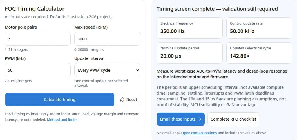
The calculation is kinematic and timing arithmetic. Bus voltage is context only: it does not enter these formulas. No inductance, back-EMF, current ripple, torque or loss model is included. The same timing arithmetic applies to silicon and GaN stages.
| Output | Formula | Limit |
|---|---|---|
| Electrical frequency (Hz) | RPM × pole pairs ÷ 60 | Mechanical speed magnitude; does not model rotor slip or feedback error. |
| Control update rate (kHz) | PWM kHz ÷ update divider | Assumes a regular schedule with one update every 1, 2 or 4 cycles. |
| Nominal update period (µs) | 1000 ÷ control update kHz | An upper interval; the usable ADC-to-PWM deadline can be shorter. |
| Updates per electrical cycle | Control update Hz ÷ electrical Hz | Undefined at zero RPM; unrelated to a guaranteed closed-loop bandwidth. |
| Review flags | Ratio <10; nominal period <15 µs | Editorial screening assumptions. If both apply, the ratio review is shown first. |
These flags are not derived from a manufacturer rating. For validation methods, TI TIDM-02007 shows frequency-response measurement and timing optimization on specific hardware.
Illustrative inputs for the calculator, not tested customer projects. Re-enter these values to reproduce the results.
| Inputs | Calculated result | Next step |
|---|---|---|
| 7 pole pairs; 3,000 RPM; 50kHz; divider 1 | 350 Hz electrical; 50kHz update; 20 µs period; 142.86 updates/cycle. | No planning flag. Benchmark firmware and verify current-loop response. |
| 21 pole pairs; 20,000 RPM; 20kHz; divider 1 | 7,000 Hz electrical; 20kHz update; 50 µs period; 2.86 updates/cycle. | Ratio review. Revisit speed, schedule and controller tuning; increasing PWM alone is not proof of stability. |
| 7 pole pairs; 3,000 RPM; 100kHz; divider 4 | 350 Hz electrical; 25kHz update; 40 µs period; 71.43 updates/cycle. | Verify the divided schedule against motor dynamics and real PWM latch deadlines. |
This is a comparison framework, not a benchmark. No matched 24V silicon/GaN measurements for this PCBA are available here. EPC’s application note provides a concrete GaN implementation; it does not rate all silicon designs.
| Decision dimension | Silicon option | GaN option |
|---|---|---|
| Switching and motor ripple | Retain if the qualified PWM rate meets the measured ripple and noise target. | Evaluate higher PWM where ripple is limiting; measure added switching and motor losses. |
| Dead-time and distortion | Characterize driver/device delays and resulting waveform distortion. | Characterize the selected stage; do not copy a sub-20 ns setting from a different board. |
| Efficiency and thermal margin | Unknown here; obtain a loss map at the intended duty cycle. | Unknown here; reference-board peak efficiency is not an OEM board rating. |
| Current sensing | Check shunt range, settling, noise and sample visibility. | Check the same constraints plus fast common-mode transients. |
| Total project cost | Existing firmware, supply chain and qualification may reduce rework. | Compare BOM, stack-up, assembly, fixtures, EMI work and firmware validation. |
Reviewed 2026-09-21. Public reference designs are evidence of their stated configurations. They are not GanServo production test reports, current inventory or a certification claim.
| Source | Supports | Boundary |
|---|---|---|
| TI TIDM-02007 — fast current loop | Demonstrates measured control response and ADC-to-PWM latency optimization using FCL and SFRA. | Specific TI hardware and software. Does not validate this tool’s 10× or 15 µs planning flags or an OEM board. |
| TI TIDUCE7B — TIDA-00909 design guide (2017) | Sections 4.2.1 and 4.3.1 separate 24V switching tests from the 48V efficiency analysis. A 12.5 ns deadband is used in this reference design. | The 98.5% value at 100kHz is a theoretical maximum at 48V, 400W input in section 4.3.1, not a measured efficiency guarantee for a 24V GanServo PCBA. |
| TI TIDA-00913 — in-line phase current sensing | INA240-based in-line sensing with PWM rejection supports switching up to 100kHz in the reference design. | Amplifier settling and sampling windows must be verified on the intended board; low-side sensing is an alternative, not a universal requirement. |
| TI SNVA729A — LMG5200 layout (2015) | Explains local decoupling, short return paths and thermal vias. More vias alone do not remove board-to-ambient thermal resistance. | Its thermal example is a 48V-to-5V buck converter. Do not transfer its efficiency or thermal result to a motor inverter. |
| EPC How2AppNote 026 — compact BLDC drive (2022) | EPC9145 illustrates power-stage layout, selectable phase/leg shunts and a defined heatsink interface. | A reference board using discrete EPC2206 devices; it is not evidence of EPC2152/EPC23102 or GanServo board performance. |
Efficiency evidence correction: TI’s overview highlights “up to” efficiency; its detailed guide labels the 98.5% value as theoretical under a 48V condition. Use the guide’s test conditions and section 4.3.1 before making any comparison. This page makes no 24V efficiency promise.
The calculator cannot qualify voltage or current capability. The following is a proposed review checklist; limits must come from the selected components and measured system behavior.
| Item | Known on this page | Required before approval |
|---|---|---|
| DC bus | 24V nominal project class only. | Supply min/max, battery charge voltage, regenerative rise, transients and protection strategy. |
| Motor and load | Pole pairs and maximum speed entered by the visitor. | R/L with measurement basis, back-EMF, RMS/peak phase current, torque-speed duty and load inertia. |
| Board and cooling | Custom PCBA inquiry, no released board rating. | Envelope, housing interface, ambient temperature and thermal test plan. |
| Feedback and firmware | Regular update-divider model only. | Encoder/position sensing, startup method, communication load and measured latency. |
Choose 24V or a higher bus from voltage headroom, current and system constraints; there is no universal 500W dividing line in this report.
Copied dead-time and layout assumptions can leave inadequate switching margin. Measure switching under the intended operating conditions and use the chosen device guidance. TI layout guidance.
Blind/buried vias or metal-core construction are not specified by this page. Review a manufacturable thermal path with the assembler, then compare prototype, fixture and qualification costs. EPC thermal interface example.
Low-side shunts need usable sampling windows; in-line shunts need suitable common-mode rejection and settling. Compare both against your duty cycle. TI’s in-line alternative.
Send the timing inputs and identify unknown values explicitly. This is a custom engineering inquiry: output ratings, firmware coverage, price, MOQ and lead time require confirmation.
| Package | Supply | Agree before release |
|---|---|---|
| Electrical and control | Motor data, bus envelope, phase current, feedback and timing result. | Measured current response, timing margin, regeneration and fault tests. |
| Mechanical and thermal | Envelope, connectors, mounting, ambient and duty cycle. | Fit check and thermal measurements in the intended housing. |
| Manufacturing | Quantity, stack-up constraints, assembly files if available. | DFM review, inspection criteria, current-sense calibration, programming and functional fixture coverage. |
| Commercial | Prototype/pilot quantities, destination and target date. | Quote scope, NRE/fixture costs, deliverables and lead time. |
Related scope: 24V actuator board · Micro GaN servo PCBA · Envelope integration guide.
No. It computes electrical frequency, control update rate and a nominal period. Stability also depends on the motor model, gains, feedback, delays and operating point. Validate the current loop on hardware.
No. PWM frequency is the switching carrier. The update rate is how often the controller runs. Closed-loop bandwidth describes the measured response; it cannot be inferred from either rate alone.
These are editorial planning thresholds for this screen, not vendor specifications or universal design rules. Ten updates per electrical cycle prompts a ratio review; a period under 15 µs prompts a timing review. Passing either flag is not hardware approval.
Yes. Electrical frequency is zero and updates per electrical cycle is N/A. The tool still shows the update rate and period. It does not assess holding torque, sensorless startup or rotor-position accuracy.
This screen accepts 1–21 pole pairs, 0–20,000 RPM and 20–150kHz PWM, as whole numbers. These are tool limits, not a product rating. Send out-of-range parameters and the motor data for an engineering review.
Yes, if the controller is designed and validated for that schedule. Select one update every 1, 2 or 4 PWM cycles. Double updates per cycle, jitter and irregular schedules are outside this model.
No universal winner is established here. Compare complete board losses, motor ripple, cooling, EMI, component cost and validation effort at the same load. Keep a qualified silicon design if it meets the application requirements.
Do not assume pin, gate-drive or protection compatibility. Review the chosen devices, switching waveforms, layout and timing as a system; a replacement requires board-level validation.
No specific MCU or arithmetic architecture is prescribed. Select timer, ADC and compute resources using measured worst-case execution and sampling-to-update latency, including other firmware workloads.
No. TI TIDA-00913 demonstrates in-line sensing at up to 100kHz PWM. Choose the topology after checking common-mode rejection, settling time and duty-dependent sample visibility on your board.
No. Specify supply tolerance or battery charge range, regeneration and transients. Review protection thresholds, capacitors and semiconductor ratings against the complete operating envelope.
No GanServo test dataset or released configuration is provided on this page. Those values, firmware support, unit price, MOQ and delivery time remain subject to project review and an agreed validation plan.
Inquiry Email
Include target torque/speed, quantity, and delivery location.