

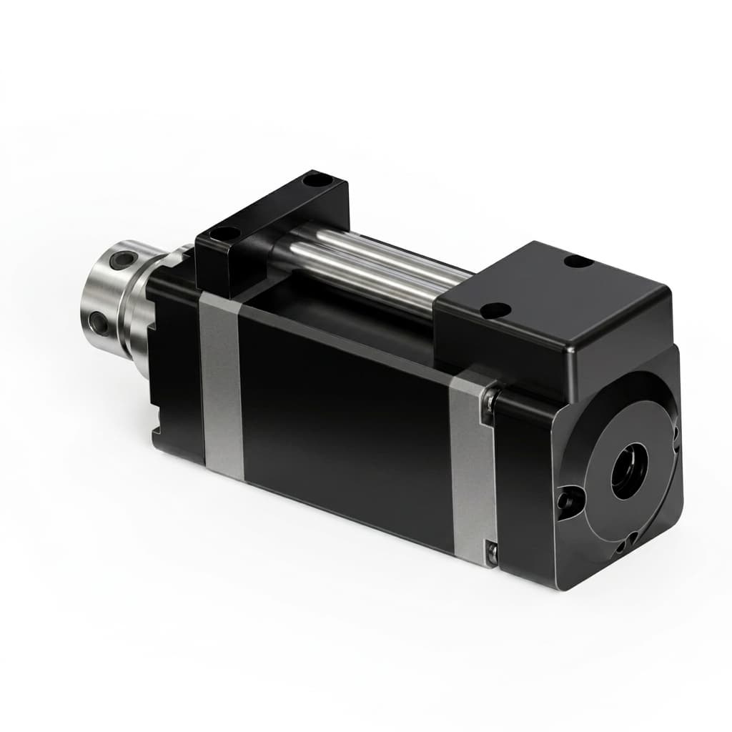
Managing EMI/EMC Compliance in High-Frequency GaN Servo Drives for Mobile Robotics
GaN servo EMI/EMC guide for robotics teams: specify 48V drives, review PCB layout, gate shaping, SSFM, and vendor evidence before CE/FCC compliance testing.
For robotics engineering and procurement teams, the transition to Gallium Nitride (GaN) micro servo drives is driven by a critical mandate: maximize power density, eliminate bulky heatsinks, and reduce harness weight in Autonomous Mobile Robots (AMRs) and humanoid platforms. The ability of GaN transistors to switch a 48V DC bus at frequencies exceeding 100kHz with near-zero reverse recovery losses offers a profound leap in actuator performance.
However, this high-speed switching introduces a significant engineering hurdle that often catches teams off guard during late-stage prototyping: Electromagnetic Interference (EMI) and Electromagnetic Compatibility (EMC) compliance.
The very characteristic that makes GaN so efficient—its ultra-fast voltage slew rate ($dV/dt$) often exceeding 100 V/ns—can turn a robotic joint into a broadband radio transmitter if not properly managed. When EMI causes sensor noise, communication dropouts on EtherCAT networks, or failure during CE/FCC compliance testing, the resulting project delays and redesign costs can easily erase the initial benefits of the GaN transition.
Executive Summary (TL;DR)
- The ultra-fast switching speeds (>100 V/ns dV/dt) of GaN devices generate high-frequency noise that can compromise robotic sensor integrity and fail EMC certifications.
- Traditional silicon mitigation strategies (large LC filters) add unacceptable weight and volume, defeating the purpose of utilizing GaN in compact humanoid and AMR joints.
- Effective EMI mitigation in GaN servos requires a holistic, embedded approach: ultra-tight PCB power loop layouts, active gate drive shaping, and spread-spectrum frequency modulation.
- Procurement teams must shift from evaluating standalone 'drive volume' to evaluating 'system-level EMC volume', requesting comprehensive EMI test reports and layout validation from suppliers.
Report Scope & Update (July 2026): This technical guide is designed for hardware system architects, compliance engineers, and supply chain directors tasked with sourcing and integrating 48V GaN servo architectures. It covers the physical mechanisms of high-frequency EMI, embedded mitigation strategies, and a strict vendor validation framework for smoother CE/FCC certification paths. It does not replace accredited lab testing, and it does not cover line-voltage industrial robot drives or stationary cabinet servo systems.
If your team is struggling with EMC compliance in a current humanoid or AMR prototype, compare your drive's architecture against our EMC-optimized 48V bare-board GaN servo driver, or contact our engineering team to request a compliance-tested evaluation kit.
1. The Physics of EMI in GaN Motor Drives
To effectively specify and procure GaN drives, one must first understand the physics of why they generate noise differently than traditional Silicon (Si) MOSFETs. Electromagnetic Interference (EMI) in motor drives is broadly categorized into two types: Conducted Emissions (noise traveling back through the battery cables) and Radiated Emissions (noise broadcasting through the air).
The Role of High $dV/dt$ and $di/dt$
In a standard silicon drive operating at 24V and 20kHz, the transistor takes a relatively long time to transition from "off" to "on." This slow transition generates heat (switching loss) but naturally limits the high-frequency energy released.
Gallium Nitride (GaN) eliminates this switching loss by turning on and off in mere nanoseconds. This produces extreme voltage slew rates ($dV/dt$) and current slew rates ($di/dt$). According to Fourier analysis, a faster square wave edge contains higher-frequency harmonic energy. In GaN systems, these harmonics can extend well into the hundreds of megahertz (MHz) or even gigahertz (GHz) range.
Parasitic Ringing and Common-Mode Noise
When these ultra-fast edges interact with parasitic elements on the Printed Circuit Board (PCB)—such as the microscopic inductance of a copper trace or the capacitance between a heat pad and the chassis—they cause severe high-frequency ringing.
Furthermore, the high $dV/dt$ applied to the motor windings creates Common-Mode (CM) Noise. This high-frequency noise capacitively couples through the motor stator directly into the robot's mechanical chassis. If the robot chassis is not properly grounded (a common scenario in mobile, battery-operated AMRs), this common-mode noise will seek a return path through sensitive encoder cables, CAN/EtherCAT data lines, or LiDAR sensor grounds, causing erratic robot behavior and software faults.
The Bearing Current Threat
An often-overlooked consequence of unmitigated high $dV/dt$ in robotic joints is Electrical Discharge Machining (EDM) inside the motor bearings. High-frequency common-mode voltages can break down the thin layer of lubricating grease inside the bearing, causing micro-sparks that physically pit the steel balls. Over time, this leads to premature mechanical bearing failure—a catastrophic issue for procurement teams expecting a 20,000-hour MTBF (Mean Time Between Failures).
2. Why Legacy Silicon Filters Fail in GaN Architectures
When faced with EMI issues, a traditional silicon-era engineering response is to add massive passive filters: heavy common-mode chokes on the battery input, and large LC sine-wave filters on the motor output.
For GaN-based robotics, this approach is fatally flawed:
- Weight and Volume: Adding a large ferrite choke and high-voltage capacitors to a micro servo drive instantly destroys the volume and weight savings that justified the GaN premium in the first place.
- High-Frequency Ineffectiveness: Traditional bulky filters are often ineffective at the >100MHz frequencies generated by GaN, as their own parasitic capacitance causes them to act like antennas rather than filters at those bands.
- Thermal Density: The filters themselves dissipate heat, requiring additional thermal management inside the already constrained robotic joint.
Instead of filtering noise after it has been created, next-generation GaN servo drives must suppress EMI at the source directly within the silicon and PCB layout.
3. Advanced Embedded Mitigation Strategies
Top-tier GaN servo manufacturers employ a multi-layered, embedded approach to EMC compliance. Procurement teams should mandate that these specific design methodologies are present in any prospective supplier's architecture.
A. Nano-Scale PCB Layout Optimization
The first and most critical line of defense is the PCB layout. The physical loop between the GaN FETs, the high-frequency ceramic decoupling capacitors, and the return path is known as the "Power Loop." In GaN designs, this loop must be measured in millimeters. The best suppliers utilize advanced 6-layer or 8-layer PCB stack-ups, placing solid ground planes immediately adjacent to the switching nodes. This ultra-low impedance return path cancels out magnetic fields, drastically reducing radiated emissions.
B. Active Gate Drive Shaping
Rather than slowing down the GaN FET permanently (which would ruin its efficiency), advanced gate drivers dynamically control the turn-on and turn-off profiles. By employing multi-stage gate resistors or active current shaping, the driver can slightly round the corners of the switching pulse. This targeted "softening" eliminates the highest-frequency ringing while preserving 98%+ overall inverter efficiency.
C. Spread Spectrum Frequency Modulation (SSFM)
Instead of switching at exactly 100.00 kHz, the drive's firmware continuously "jitters" the switching frequency between, for example, 95 kHz and 105 kHz. By spreading the noise energy over a wider frequency band, the peak amplitude of the EMI is significantly reduced. This firmware-level technique costs zero weight and zero board space, yet is often the difference between passing and failing CISPR or FCC radiated emissions tests.
D. Z-Axis Shielding and Equipotential Bonding
For the most sensitive humanoid platforms, physical containment is still required, but it must be miniaturized. Advanced GaN drives utilize low-profile, board-level Faraday cages (shielding cans) soldered directly over the inverter bridge. Additionally, the drive must feature defined equipotential bonding points to ensure the motor casing, drive ground, and robot chassis maintain a unified zero-volt reference, preventing common-mode loops.
4. Visualizing the GaN EMI Mitigation Architecture
5. Comparative Evaluation: System-Level EMC vs. Standalone Volume
A frequent trap for procurement teams is selecting a GaN drive based purely on the volume of the bare PCBA. A drive that is 10% smaller but lacks embedded EMI mitigation will ultimately require an external LC filter that is 300% the size of the drive itself.
When evaluating suppliers, use this structured comparison matrix to ensure you are assessing the True System-Level Volume and risk profile.
| EMI Mitigation Dimension | Commodity Silicon (24V/48V) | Unoptimized GaN (High Risk) | EMC-Optimized GaN (Next-Gen) | Procurement Impact & Action |
|---|---|---|---|---|
| Primary EMI Strategy | External bulky LC filters & Chokes | None, or relies entirely on customer chassis | Embedded (PCB layout, Gate shaping, SSFM) | BOM Optimization: Optimized GaN eliminates the need for expensive, heavy external filtering components. |
| $dV/dt$ Control Method | Inherent slow switching (high thermal loss) | Fixed, fast switching (High EMI risk) | Dynamic/Active Gate Resistor Tuning | Risk Reduction: Active tuning allows fine-tuning for compliance without redesigning the PCB. |
| Bearing Current Risk | Moderate | Extreme (High chance of premature motor failure) | Low (Controlled CM noise, mitigated edges) | MTBF/Warranty: Unoptimized GaN will destroy coreless motor bearings, leading to massive field replacement costs. |
| Radiated Emissions (RE) | Passing with standard metal housing | Fails CISPR 11/32 without heavy shielding | Passes via Spread Spectrum & tight loops | Time to Market: Optimized firmware prevents months of delay during FCC/CE testing phase. |
| System-Level Volume | Large Drive + Moderate Filter | Small Drive + Massive External Filter | Ultra-Small Drive + Zero External Filter | Mechanical Integration: Only EMC-optimized GaN actually delivers the promised spatial savings for humanoid joints. |
| Data/EtherCAT Integrity | Stable | High packet loss due to CM noise injection | Stable (Equipotential bonding prevents ground loops) | Software Stability: Clean drives prevent mysterious software faults and robot "stutters" on the factory floor. |
6. Supplier Validation Checklist for GaN Servo Actuators
Before approving a GaN servo vendor for your next AMR or humanoid pilot program, engineering and supply chain managers must demand verifiable data. Use the following checklist during your Technical RFQ process.
- Request Pre-Compliance Scan Data: Does the supplier provide conducted and radiated emissions scans (CISPR 11/22/32) of the bare drive operating a representative motor at full 48V bus voltage?
- Verify PCB Stack-Up: Ask the vendor for their PCB layer count and layout philosophy. Are they using 6+ layers with dedicated adjacent ground planes to minimize the GaN power loop inductance?
- Check for Spread Spectrum Modulation (SSFM): Is SSFM implemented in the firmware, and can it be toggled or tuned via the communication bus (e.g., EtherCAT/CANopen) during compliance testing?
- Assess Gate Drive Topology: Do they use static gate resistors, or do they employ active gate shaping to manage $dV/dt$ without crippling the >100kHz frequency advantages?
- Verify Motor Cable Shielding Protocols: Does the vendor provide explicit documentation on how to terminate the 360° shield of the motor phases directly to the drive's equipotential ground?
- Inquire about Common-Mode (CM) Noise: Ask how they mitigate CM voltage injection into the motor stator to prevent bearing degradation.
7. Frequently Asked Questions (FAQ)
Q: Can we just use a standard 48V EMI filter from our silicon architecture on a new GaN drive?
A: No. Standard EMI filters are designed to attenuate lower-frequency harmonics (e.g., 20kHz to 1MHz). GaN drives generate harmonics well above 100MHz. The parasitic capacitance inside legacy filters often renders them useless at these high frequencies. GaN requires high-frequency ceramic decoupling and embedded layout solutions.
Q: Does Spread Spectrum Frequency Modulation (SSFM) affect the precision of the robot's movement?
A: For high-quality drives, no. SSFM jitters the switching frequency (e.g., by $\pm 5%$), but the underlying current control loop and FOC (Field Oriented Control) algorithms operate fast enough to reject this variance, ensuring zero impact on joint positioning accuracy or torque ripple.
Q: We are using plastic joints/housings to save weight. Can we still pass EMC with GaN?
A: It is significantly harder. If the joint housing is non-conductive, it cannot act as a Faraday cage. In this scenario, you must select a GaN drive that features board-level shielding cans and flawless PCB-level emissions control, as you cannot rely on the chassis to block radiated noise.
Q: How does EMI affect our EtherCAT network?
A: Unmitigated high $dV/dt$ creates common-mode noise that travels through grounds. If the drive and network cables are improperly grounded, this noise induces voltage spikes on the differential EtherCAT pairs, causing packet loss, high error frame counts, and eventual network desynchronization, which triggers emergency safety stops in the robot.
8. Sourcing Your Next-Generation Architecture
The physical reality of Gallium Nitride is clear: it offers unmatched power density and efficiency for 48V robotic architectures, but only if the manufacturer has mastered the deep electrical engineering required to tame its electromagnetic emissions. Procurement teams that prioritize embedded EMC design will drastically reduce their Total Cost of Ownership (TCO) by avoiding late-stage filtering, certification failures, and warranty claims.
Ready to test a drive built from the ground up for compliance? Review our Ring-Shaped Humanoid Joint PCBA specifically designed for confined spaces, or Contact GAN Servo Engineering today to discuss your payload, voltage, and EMC certification requirements.
Sources & References
- Texas Instruments (TI): How three-phase integrated GaN technology maximizes motor-drive performance - Technical overview of integrated GaN motor-drive performance, power density, and implementation trade-offs.
- Texas Instruments (TI): Engineer's guide to low EMI in power supply designs - Practical reference for layout, filtering, and spread-spectrum techniques used to reduce peak emissions in high-frequency power electronics.
- Electronic Code of Federal Regulations (eCFR): 47 CFR Part 15 - Radio Frequency Devices - Official U.S. regulatory framework relevant to unintentional radiators and FCC compliance planning.
Author

Categories
More Posts
GaN vs. Silicon Servo Drives in Mobile Robotics: A Procurement Cost-Benefit Analysis
Compare GaN vs. silicon servo drives for mobile robots. Review TCO, battery, thermal, payload, supplier checks, and request a GAN Servo evaluation kit.
Thermal Management Strategies for Micro GaN Servo Drives in Robotic Joints
Actionable stack-up and firmware strategies for managing heat dissipation in ultra-compact GaN-based servo PCBA stacks for humanoid robots and cobots.
AEC-Q101 GaN Servo Drives in Robotics: The 2026 Procurement Guide
Why mobile robotics and AMR buyers are demanding automotive-grade AEC-Q101 GaN servo drives. Compare TCO, lifecycle, and supplier vetting strategies.