

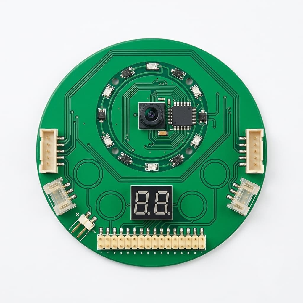
Regenerative Braking and DC-Bus Overvoltage in 48V GaN Servo Drives: Sizing Brake Choppers, Zero-Avalanche Protection, and Robotics Sourcing
Size brake choppers for 48V GaN servo drives, assess bus overvoltage and BMS disconnect risks, and request evidence with a seven-point supplier RFQ checklist.
For a 48V GaN servo drive, size the regenerative energy path before selecting the brake chopper or resistor. Standard enhancement-mode GaN devices do not provide the silicon-style avalanche clamp that designers sometimes rely on. This does not mean every excursion above the nominal voltage rating causes immediate failure: any permitted transient must meet the selected device's explicit datasheet conditions. In battery-powered automated mobile robots (AMRs), automated guided vehicles (AGVs), and humanoid joints, procurement teams need evidence for bus-voltage limits, stopping energy, and resistor duty cycle.
Executive Summary (TL;DR)
- Do not budget for avalanche absorption unless the selected device explicitly supports it; transient overvoltage ratings are device-specific.
- Use effective DC-bus capacitance at operating bias: a calculated 0.25 J input raises an isolated 100 µF bus from 48 V to about 85.5 V.
- Check the battery's permitted regenerative charge current at full charge, low temperature, and BMS disconnect; the battery is not an unconditional energy sink.
- Derive chopper response time from bus capacitance, remaining voltage headroom, and peak regenerative power, then validate the complete protection path.
- Require supplier evidence for resistor resistance limits, pulse energy, repeat duty, and protection behavior when the main inverter is disabled.
Published and reviewed: October 28, 2026. Scope: An English-language engineering and procurement guide for global robotics OEMs evaluating 24V to 60V DC GaN servo drives. The numerical example uses a nominal 48V system with a 54.6V maximum source voltage. It does not apply unchanged to a 58.4V battery or to every product described as a “48V drive.”
Evidence and calculation limits: This is a source-based screening method with hypothetical, reproducible calculations, not a report of measured GAN Servo hardware performance. Effective capacitance, motor inductance, reflected inertia, battery impedance, component tolerances, and actual protection waveforms must be established for the selected assembly. The diagrams and product images do not establish an integrated chopper, safety certification, or an approved resistor rating.
Preparing an RFQ for robotic joint or mobile base motor drives? Compare your bus envelope and packaging constraints with our 24V–60V Low-Voltage GaN Servo Module or our Custom Motor Control PCBA Platform, then contact our engineering team to evaluate dynamic braking resistor (DBR) configurations and regenerative clamping margins.
1. The Physics of Regenerative Energy and DC-Bus Pumping
During acceleration and steady-state motion, electrical power flows from the DC power source (battery or DC power supply) through the three-phase inverter to convert electrical energy into mechanical torque and shaft rotation.
However, whenever a motion controller commands rapid deceleration, or an external gravitational or inertial load overhauls the motor (such as an AMR braking from full payload speed or a robotic arm lowering a vertical payload), the permanent magnet synchronous motor (PMSM) or brushless DC (BLDC) motor acts as an electrical generator.
During controlled deceleration, the inverter can return power to the DC intermediate circuit, including when motor back-EMF is below the bus voltage. This is DC-bus pumping. TI's motor regeneration and VM pumping analysis illustrates the mechanism using a brushed-motor H-bridge; it is background physics, not validation of a three-phase GaN drive.
Kinetic Energy in the Mechanical System
The mechanical energy released by a rotating shaft and its reflected load is:
E_mech = 0.5 × J_total × (omega_1² - omega_2²)
E_regen = E_mech × eta_total
Where:
J_totalis inertia reflected to the motor shaft in kg·m², including rotor, gearbox, and payload.omega_1andomega_2are initial and final shaft speeds in rad/s.eta_totalis the mechanical-to-bus regeneration efficiency, established for the operating point; it is not round-trip efficiency.
For a mobile base, include translational energy (0.5 × mass × speed²) without double-counting it as reflected inertia. For a descending axis, also include released gravitational potential energy (mass × g × height). Sum simultaneous stops on a shared bus. If losses are unknown, use the full available mechanical energy as a conservative screening input rather than assuming a typical efficiency discount.
Returned energy must go into an accepting battery or supply, bus capacitance, another motoring axis, or a braking load. Loss of one path changes the demand on the others.
2. Why GaN Servo Drives Face Unique Overvoltage Vulnerabilities
The main risks are a lack of avalanche clamping, limited local energy storage, and loss of the intended energy sink. These require separate checks; selecting GaN alone does not determine the capacitance or protection response time.
A. Zero-Avalanche Protection: Use the Actual Device Ratings
Some silicon MOSFETs specify single-pulse avalanche energy under defined current and temperature conditions. That rating does not authorize arbitrary repetitive braking energy absorption. Standard enhancement-mode GaN HEMTs do not offer the same avalanche mechanism, so the design must not rely on it.
Absence of avalanche is not absence of all transient overvoltage capability. EPC's Phase 18 reliability report, section 4.2.4 discusses repetitive transient drain-voltage specifications for particular devices. Apply only the chosen part's stated voltage, duration, duty, and temperature conditions. Do not transfer another device's test result to your BOM or infer a universal nanosecond failure time.
B. The "Capacitor Trap": MLCC Density vs. Stored Energy
Higher switching frequency can reduce ripple-filter requirements, but it does not remove the bulk energy-storage requirement during braking. A compact drive may have a small MLCC bank, a hybrid bank, or external bulk storage. Request its effective bus capacitance at voltage and temperature, not an assumed value based on semiconductor type. Murata's DC-bias explanation shows why nominal Class II MLCC capacitance can overstate available capacitance.
For constant effective capacitance and energy that cannot escape to another sink:
V_final = sqrt(V_initial² + 2 × E_regen / C_bus)
Delta_V = V_final - V_initial
Numerical Reality Check: The 100 µF Vulnerability
Assume a 48V bus, an effective capacitance of 100 µF (0.0001 F), and 0.25 J of returned energy. This is a hypothetical isolated-bus calculation:
V_final = sqrt(48² + 2 × 0.25 / 0.0001) = 85.46 V
Delta_V = 85.46 - 48 = 37.46 V
The idealized final voltage is 85.5V, not a measured waveform or an instantaneous step. The rise time depends on regenerative power. This is outside an 80V continuous voltage envelope and may also exceed driver, capacitor, or connector limits. A 100V switch does not by itself make the assembled drive safe: switching overshoot and all component limits still need verification. If capacitance changes materially with voltage, use the capacitor's charge/energy curve rather than this constant-capacitance approximation.
C. The Battery Management System (BMS) Disconnect Hazard
In autonomous mobile robots (AMRs, AGVs) and battery-powered quadrupeds or humanoids, engineers often assume: "We are on a 48V lithium battery pack; the battery will absorb all regenerative current like an infinite sink."
Check three operating conditions against the actual pack and BMS specification:
- Full State of Charge: The allowed charge current can fall or the charge path can open near the pack's cell-voltage limits. Thresholds, delays, and switch topology vary.
- Cold-Temperature Charge Inhibit: The BMS may prohibit or limit charging. Confirm the permitted current over the specified temperature range.
- Supply Isolation During a Stop: A contactor, interlock, cable fault, or reverse-current blocking input stage can remove the battery as a sink. Determine what remains connected on the drive side.
If regeneration continues after the sink disappears, local capacitance and the remaining braking circuit must handle it. A disabled inverter does not necessarily return all kinetic energy to the bus; the path depends on back-EMF, switching state, and circuit topology.
3. Conceptual Architecture: Fast Hardware Clamping and Dynamic Braking
An independent hardware chopper can handle bus energy while motion control limits regeneration during normal operation. Fast switching overshoot also needs suitable layout, decoupling, and any required snubber or clamp: a brake resistor is not a substitute for those measures.
Figure 1: Conceptual architecture, not a product schematic. Numerical labels illustrate the 54.6V maximum-source example in Section 4; they are not universal settings or measured product specifications. The blocks show functions, not complete wiring. The DBR branch and its control supply must remain connected to the drive-side bus after upstream isolation.
Derive the Protection Response Budget
Energy alone cannot establish a rise time. For approximately constant regenerative power and capacitance, the unopposed time from chopper turn-on voltage to the maximum permitted bus voltage is:
t_headroom = C_bus × (V_limit² - V_on²) / (2 × P_regen)
Example: 0.0001 × (60² - 57²) / (2 × 600) = 29.25 µs
This hypothetical 29.25 µs is the whole energy headroom, not an acceptable comparator delay. Reserve margin for sensing tolerances, filtering, gate-driver delay, current build-up, and overshoot. Less capacitance or higher incoming power shortens it. Test the complete path at worst-case conditions.
An autonomous analog comparator or a validated hardware peripheral avoids dependence on a firmware polling task. Firmware response can be acceptable only if its worst-case latency, failure behavior, and voltage margin are demonstrated. Neither a universal “under 500 ns” requirement nor a fast comparator alone guarantees survival.
4. Engineering Sizing Guide: Calculating Dynamic Brake Resistors
To specify a dynamic braking resistor (DBR) and qualify whether a supplier's internal or external chopper circuit meets your application's duty cycle, follow this step-by-step engineering derivation.
Step 1: Establish Voltage Operating Windows
Illustrative assumptions only: maximum source voltage 54.6V; validated assembled-drive bus ceiling 60V; effective capacitance 100 µF. Establish the ceiling from the lowest relevant component limit, not just the GaN transistor rating. The settings below require a tolerance and overshoot budget before use.
| Parameter | Illustrative value | Engineering purpose / acceptance evidence |
|---|---|---|
| Nominal bus | 48.0 V | Identify actual pack series count and chemistry. |
| Maximum source voltage | 54.6 V | Include charger accuracy and operating tolerance. |
| Chopper turn-off | 55.5 V | Keep its lowest tolerance limit above the highest normal source voltage. |
| Chopper turn-on | 57.0 V | Include divider/reference error and dynamic response. |
| Overvoltage fault threshold | 59.0 V | A fault stops commanded operation; it does not absorb residual energy. |
| Permitted bus ceiling | 60.0 V | Include ripple and overshoot; verify every exposed component. |
| Example GaN device rating | 100 V | Illustrative switch choice; does not make the drive a 100V-rated assembly. |
| Effective bus capacitance | 100 µF | Verify at DC bias, temperature, tolerance, and aging. |
The intended order is maximum source < turn-off < turn-on < fault threshold < permitted bus ceiling, with adequate separation after tolerances. A 58.4V source is incompatible with this example's 57V turn-on threshold. Recalculate the whole window or select a different drive; do not simply raise the clamp above the assembly's permitted voltage.
Step 2: Calculate Peak Braking Power
For a stop from initial speed to zero with constant deceleration torque and approximately constant regeneration efficiency, returned power declines linearly with speed:
P_peak = 2 × E_regen / t_stopFor a hypothetical axis returning 45 J in 0.15 s, peak power is 600 W, while average power during the stop is 300 W. Assume no battery or other axis absorbs it. For an S-curve stop, a descending load, changing efficiency, or multiple axes, use the actual worst-case power envelope instead of this peak formula.
Step 3: Determine Braking Resistor Value
Select resistance between the current-limited lower bound and power-limited upper bound. Use the highest possible voltage for current and the lowest clamping voltage for power. Respect the drive manufacturer's minimum resistance even if a transistor's standalone rating appears to permit less. SEW-EURODRIVE's BCSA-060-10-00 technical data provides a concrete example of separately specified peak current, continuous current, threshold tolerance, and minimum resistance; those ratings do not transfer to another chopper.
R_min = V_high / I_allowed
R_max = D_max × V_low² / P_peak

Example assumptions: V_high = 60 V; V_low = 55.5 V;
I_allowed = 25 A for the required pulse; D_max = 1.
R_min = 60 / 25 = 2.40 ohm
R_max = 55.5² / 600 = 5.13 ohm
D_max is the maximum supported chopper duty during the braking interval. A lower duty limit reduces R_max; if R_min exceeds R_max, the assumed chopper is unsuitable. Apply resistance tolerance, hot resistance, and voltage tolerances to both bounds.
Candidate, not approved part: a 3.9 ohm, ±5% resistor has 3.705–4.095 ohm initial resistance. Ignoring temperature drift, its worst-case current at 60V is 16.2 A and its minimum on-state power at 55.5V is 752 W, above the assumed 600W demand. The resistor still needs a documented 45 J / 150 ms pulse capability for the actual waveform, thermal mounting, and repeat duty; check the chopper's current and thermal ratings for the same duration.
Step 4: Check Pulse Energy and Repeated Thermal Load Separately
A braking resistor must survive not just the single-pulse peak wattage, but the long-term continuous thermal build-up across the machine's operating cycle.
P_average = E_absorbed_per_stop / t_cycleFor 45 J every 300 s, average dissipation is 0.15 W. This low average does not establish survival of the 45J pulse. For 45 J every 1.2 s, average dissipation is 37.5 W. An illustrative 1.4 design allowance gives 52.5 W, but the selected resistor's manufacturer derating curve and actual heat sink determine the required nameplate rating. A generic safety multiplier cannot replace those data.
Require pulse-overload curves, allowed initial temperature, repeated-pulse limits, resistor temperature protection, and chopper thermal data. An open resistor, disabled chopper, or lost control supply needs a defined fault response. ABB's Electrical braking guide, sections 3.2 and 4 discusses chopper duty and thermal sizing in industrial drives; its mains-drive examples are not low-voltage product ratings.
For an RFQ review, send the engineering team your energy, stop time, repeat interval, source-voltage range, and mounting conditions, together with the candidate supplier's resistor and chopper limits.
5. Architectural Comparison Matrix: Overvoltage Mitigation Topologies
Use this qualitative selection matrix to ask for evidence. It is not a measured cost, response-time, or energy-capacity comparison.
| Energy path / topology | Appropriate role | Key limit | Supplier evidence to request |
|---|---|---|---|
| TVS or other transient clamp | Limit short transients within its pulse rating | Pulse duration, clamp voltage at current, repetition, temperature | Actual pulse curve and measured device voltage; do not assume it handles a full stop |
| Local or external capacitor bank | Buffer finite energy between source and permitted bus voltage | Effective capacitance, voltage rating, inrush, volume | Energy calculation and bias/temperature capacitance data |
| Integrated chopper + external DBR | Dissipate energy locally when the source cannot accept it | Minimum resistance, pulse current, duty, thermal mounting | Full protection-path waveform and resistor pulse qualification |
| External bus chopper module | Add a dissipative sink to a drive without an internal chopper | Cable inductance, connection location, control-power continuity | Compatibility declaration and worst-case bus overshoot at each drive |
| Shared DC bus | Transfer energy to axes that are motoring at the same time | No guaranteed sink if all axes brake together | Simultaneous-stop energy balance and fallback dissipation |
| Bidirectional supply or accepting battery | Recover energy into the source | Charge limits, full charge, temperature, isolation behavior | Guaranteed sink-current envelope and fallback test with sink unavailable |
6. Software Braking vs. Hardware Choppers: Flux Braking in FOC
Can motion control firmware eliminate the need for a braking resistor through advanced motor control algorithms?
Some drives deliberately increase motor losses to reduce the energy returned to the bus. The available method depends on the motor type and control implementation.
How Flux Braking Works
ABB's guide describes increasing motor flux and losses to dissipate energy in the motor. This is not a universal instruction to inject large negative I_d into a PMSM: negative I_d weakens permanent-magnet flux and needs motor-specific limits. Ask which method the drive supports.
The Engineering Trade-offs of Flux Braking
- Thermal load: Repeated loss-based braking heats the windings.
- Operating limits: Available braking depends on speed, motor parameters, current limits, and active control.
- Disabled inverter: Do not count an actively controlled loss path after STO or loss of gate-drive power.
7. Supplier RFQ Sourcing Checklist: 7 Technical Verifications
When issuing a Request for Quotation (RFQ) for 24V–60V GaN servo drives for dynamic robotics applications, use this 7-point technical verification checklist to ensure supplier claims are backed by hardware-level validation.
- 1. Device voltage envelope: Obtain the exact power-device and gate-driver part numbers, continuous and transient voltage conditions, and measured worst-case switching overshoot. A 100V GaN device can be a candidate for a 48V bus, but its rating alone cannot approve the assembly.
- 2. Chopper implementation: Confirm whether the drive includes a power switch or only a control output. Request end-to-end response timing, threshold tolerances, and operation during MCU reset, STO, and upstream supply isolation.
- 3. Resistor limits: Obtain the permitted minimum resistance, maximum supported duty, pulse-current limit, connector rating, and wiring instructions. Compare the resistor's cold/hot tolerance range against both calculated bounds.
- 4. Effective capacitance: Request the bus-capacitor BOM and effective capacitance at operating DC bias, temperature, tolerance, and aging. Calculate unbuffered energy capacity between the actual operating and permitted bus voltages.
- 5. Lost-sink validation: Request controlled laboratory captures of full-charge operation, charge inhibit, and source isolation during the specified deceleration. Record bus voltage at the drive, regenerative current, load, initial speed, probe setup, and chopper current.
- 6. Stop-function coordination: Obtain the selected drive's safety manual and evidence for the intended STO, SS1, and mechanical-brake sequence. Confirm whether the chopper stays powered and connected; an energy clamp does not establish a safety integrity rating.
- 7. Thermal and fault limits: Obtain resistor pulse-overload curves, repetition and mounting derating, chopper thermal data, and the response to an open resistor or overtemperature. Make these controlled RFQ deliverables before freezing the BOM.
8. Hardware Integration: Packaging Is Not a Chopper Specification
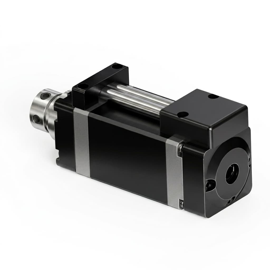
Bare-board and enclosed drives create different mounting and cooling constraints. Confirm the location of the chopper, resistor terminals, and return path from the selected assembly's schematic and manual. Do not infer internal braking capability from an enclosure photograph.
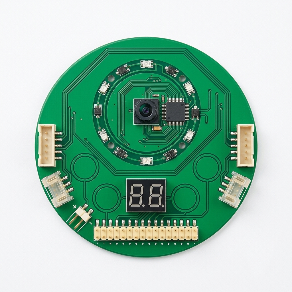
Figure 2: Packaging illustration only. This image does not demonstrate an internal chopper, resistor, thermal resistance, or measured loop inductance. Check the linked low-voltage GaN servo module against its approved configuration and request any missing braking specifications.
Mount an external resistor according to its manufacturer's heat-sink and clearance instructions. Keep its hot surfaces away from temperature-sensitive components. Locate the chopper and its supply on the drive side of any contactor that removes the normal energy sink.
9. Frequently Asked Questions (FAQ)
Can a transient voltage suppressor (TVS) diode replace a brake chopper?
Only if its documented clamp voltage, pulse energy, pulse duration, temperature derating, and repetition limits cover the entire event. TI's VM pumping article demonstrates TVS clamping in a specific small-motor setup; it does not establish suitability for a 45J robot stop. Use a qualified chopper and resistor when the transient device's capability is insufficient or unknown.
Why do ceramic MLCC capacitors lose capacitance under DC bias?
Class II dielectrics such as X5R and X7R change effective capacitance under DC voltage, as explained by Murata. The reduction depends on the exact part, package, voltage, and temperature; there is no universal percentage. Use manufacturer curves or measurements for the bus energy calculation instead of summing nominal capacitance.
What is the difference between dynamic braking and regenerative braking?
Regenerative braking returns mechanical energy to an accepting electrical source, such as a battery or bidirectional supply. Resistor-based dynamic braking dissipates returned energy as heat. A robot may use both: recover energy while the battery accepts charge, then dissipate excess energy when it cannot.
How does dead-time management in GaN inverters affect regenerative braking?
During dead time, reverse channel conduction can dissipate energy. The voltage drop and required dead time depend on the device, gate bias, driver timing, current, and temperature. Request the vendor's validated timing range and thermal results; a fixed nanosecond setting cannot eliminate all losses or provide bus overvoltage protection.
Does Safe Torque Off (STO) protect against regenerative overvoltage?
No. STO removes torque-producing drive action; it is not a bus clamp. A spinning permanent-magnet motor may still return energy if back-EMF and the remaining circuit permit conduction. Select the stop sequence from the machine risk assessment and drive safety manual. See ABB's functional safety guide, standardized safety functions.
10. Procurement and Engineering Action Plan
Before freezing the robot's drive BOM:
- Quantify energy and power: Include inertia, translating payload, gravity, simultaneous axes, the actual stop profile, and the worst case in which the battery accepts no charge.
- Approve the whole voltage envelope: Check the fully charged source, clamp tolerances, residual energy after a fault, and local device overshoot against every component's allowed conditions.
- Qualify the braking branch: Confirm the resistance interval, pulse energy, repeat duty, mounting, and controlled lost-sink test results. Keep missing supplier evidence open rather than treating a calculation as a passed hardware test.
For a purchasing decision, a supplier should return the completed seven-point checklist with configuration-specific documents and waveforms. If the voltage window or resistor interval cannot be closed, revise the energy path or choose a different assembly before release.
Sources & References
Official sources checked on October 28, 2026. They support the stated principles and examples within their own scope; none certifies the illustrated GAN Servo product or the hypothetical resistor selection.
- Texas Instruments, SSZTCH8: Motor Drive Forum Top FAQs Part 2: How to Estimate Motor Regeneration and VM Pumping, pages 1–6. Brushed H-bridge regeneration, boost behavior, and a specific TVS-clamping example; not a GaN product validation.
- Efficient Power Conversion: Reliability Report — Phase Eighteen Testing, section 4.2.4, printed pages 19–20. Absence of avalanche and device-specific repetitive transient drain-overvoltage testing; apply the selected part's datasheet limits.
- Murata Manufacturing: Does the capacitance change when a DC voltage is applied to ceramic capacitors?. Class II MLCC DC-bias behavior and the need to use actual operating conditions.
- SEW-EURODRIVE, January 2026 edition: Technical data: BCSA-060-10-00 brake chopper. Example of separate peak/continuous current, minimum resistance, and threshold tolerances; not interchangeable with another drive's ratings.
- ABB, Technical guide book, Rev I: Technical guide No. 8: Electrical braking; No. 10: Functional safety. Guide 8 sections 3.1–3.2 (PDF pages 321–324) and guide 10 standardized safety functions (PDF pages 423–424). General control, thermal, and safety-function context; not evidence of compliance for a specific robot.
Source boundary: The worked calculations are editorial derivations using explicitly stated assumptions. Confirm motor parameters, effective capacitance, component ratings, tolerances, and actual protection performance with the selected drive, battery, and braking-resistor suppliers.
Author
Categories
More Posts
Current Sensing Architectures in 100kHz–200kHz GaN Servo Inverters: In-Line Shunts, Low-Side Limits, and Isolated Magnetic ICs in Robotics Procurement
Compare GaN servo current sensing: in-line shunts, low-side limits and isolated magnetic ICs. Use timing examples and an 8-point RFQ checklist for OEM sourcing.
Supplier Validation Checklist: Qualifying an OEM for Robotic Joint Electronics
Hard data thresholds for hardware engineering and procurement teams to evaluate electronics manufacturing partners for critical robotic actuators.

48V GaN Servo Architecture for Humanoid and AMR Procurement
See why 48V GaN servo drives help humanoid and AMR teams cut harness weight, manage heat, vet suppliers, and request a 48V evaluation kit for pilot sourcing.