

1. Decision summary: choose a controller architecture, then qualify it
A 24V miniature servo controller PCBA can place current control and power conversion inside a robotic joint. The useful decision is whether integration still leaves enough room for cooling, settled sensing, timing margin, and service access. Start with the screener above, then resolve the unknowns below before fixing an enclosure or BOM.
| Conclusion | Evidence or method | Decision / next action |
|---|---|---|
| Higher PWM trades ripple against heat and timing | Shared-model frequency sweep in section 4; EPC9146 reference architecture | Choose from a measured waveform and a complete heat budget, not PWM alone. |
| Controller timing is implementation-specific | ST AN5325 and TI C2000 documentation in section 4 | Measure worst-case acquisition-to-PWM-update latency with communications active. |
| Cooling data must describe the entire assembly | Section 10: assumed aggregate thermal impedance; no test record | Obtain board-to-case and case-to-air measurements; do not infer touch safety. |
| Nominal 24 V does not settle FET voltage selection | EPC2055 component rating; section 7 transient review | Bound regeneration and ringing before selecting a voltage class. |
| Manufacturing and commercial terms remain open | Section 13 RFQ acceptance checklist; no project qualification supplied | Agree inspection coverage, standards, NRE, and validation deliverables in writing. |
Scope and date: engineering screening reviewed 8 November 2026. Numerical examples are reproducible calculations with illustrative inputs. No measured GanServo board ratings, calibrated thermal data, medical approvals, or production certifications are established by this page. Unknown motor or cooling data should go directly to an engineering review.
2. Method, assumptions, and limits
The tool models a balanced three-phase sinusoidal current with one FOC update per PWM period. Resistance is fixed at a 105 °C reference; there is no iterative junction-temperature solution. Switching energy scales linearly with current and bus voltage as a sensitivity assumption. These simplifications support comparison, not hardware sign-off.
P_cond = 3 × I_rms² × R105
R105 = 6.5 mΩ × [1 + 0.006 × (105 − 25)]
P_sw = 6 × f_pwm × 2.4 µJ × (I_rms / 6 A) × (V_bus / 24 V)
P_dt = 6 × f_pwm × 20 ns × 2 V × (2√2 / π) × I_rms
P_inv = P_cond + P_sw + P_dt
P_gate = 6 × 2 nC × 5 V × f_pwm
P_mcu = 0.35 W × f_core / 168 MHz
P_aux = (P_mcu + P_gate + 0.18 W) / 0.88
P_model = P_inv + P_aux
t_foc = 0.8 µs + 410 / f_core(MHz)
Period use = 100 × t_foc / T_pwm
ΔI_pp ≈ V_bus / (8 × L_phase × f_pwm)
T_proxy = T_ambient + P_model × R_cooling
| Quantity | Screening value / interpretation | Missing evidence |
|---|---|---|
| Current and ripple | Continuous Arms per phase; ripple p-p divided by √2 × Arms | Motor connection, inductance convention, saturation, waveform, and peak duty |
| FET model | 6.5 mΩ at 25 °C, +0.6%/°C; 2.4 µJ at 24 V / 6 Arms | Selected-device curves and measured switching energy; no EPC2055 calibration |
| Dead time | 20 ns with 2.0 V reverse drop; six effective intervals per PWM cycle | Actual switching sequence, gate timing, current direction, and device reverse drop |
| FOC latency | 410 math cycles plus fixed 0.8 µs acquisition | Compiled implementation, ADC/driver delay, encoder path, interrupts, and PWM reload deadline |
| Cooling | 5.2 or 16.5 °C/W aggregate assumptions | Contact, package hotspots, enclosure, adjacent motor heat, and air boundary conditions |
| Excluded losses | Motor, shunts, copper, connectors, filters, braking and unmodelled loads | Complete assembly power balance and thermal measurements |
The ripple equation is a simplified screening approximation. Modulation index, back-EMF, winding coupling, and sampling strategy alter actual ripple; it is not a universal worst-case SVPWM bound. Above 25% ripple, above 105 °C thermal proxy, or at a missed timing deadline, temperature is withheld. The 25% and 75% period-use triggers are editorial review thresholds. Values equal to 25%, 75%, or 105 °C are not approvals.
3. Integrated controller architecture
Integration shortens phase wiring but puts sensitive feedback and logic close to switching currents. Resolve fault shutdown, current acquisition, encoder referencing, and power sequencing alongside the inverter. A selected MCU or gate-driver datasheet does not establish the performance of the assembled controller.
The EPC reference board is substantially larger than a miniature joint controller and mates to separate control hardware. Use its functional partitions as a checklist; do not copy its current, voltage, or thermal ratings onto an OEM concept.
4. FOC timing and the PWM / ripple trade-off
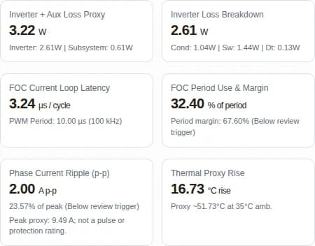
At default inputs, the assumed acquisition-plus-math path takes 3.24 µs out of 10.00 µs: 32.40% period use. This is elapsed latency, not measured CPU utilization. PWM reload timing may allow less than a full period; confirm the actual trigger and update schedule.
| Stage | Assumed cost | Qualification requirement |
|---|---|---|
| ADC acquisition / conversion | 0.80 µs elapsed | Check sensor settling, source impedance, ADC settings, and overlap with CPU. |
| Clarke / Park | 85 cycles | Confirm precision, compiler, accelerator configuration, and memory placement. |
| Dual PI | 120 cycles | Include saturation handling, anti-windup, and worst-case branches. |
| Inverse transform / SVPWM | 110 cycles | Include peripheral writes and actual timer preload deadline. |
| Filtering / observer allocation | 95 cycles | An assumed allocation; does not cover every encoder, safety, or communications task. |
| Combined elapsed path | 3.24 µs; 67.60% period margin | Measure interrupts, flash stalls, bus traffic, and missed updates; margin is not free CPU time. |
| PWM (kHz) | Ripple (A p-p / % peak) | Modelled dissipation (W) | FOC period use (%) | Review |
|---|---|---|---|---|
| 20 | 10.00 / 117.85% | 1.96 | 6.48 | High ripple; temperature withheld |
| 50 | 4.00 / 47.14% | 2.43 | 16.20 | High ripple; temperature withheld |
| 80 | 2.50 / 29.46% | 2.90 | 25.92 | High ripple; temperature withheld |
| 100 | 2.00 / 23.57% | 3.22 | 32.40 | Hardware validation required |
| 140 | 1.43 / 16.84% | 3.85 | 45.37 | Hardware validation required |
| 160 | 1.25 / 14.73% | 4.16 | 51.85 | Hardware validation required |
| 200 | 1.00 / 11.79% | 4.79 | 64.81 | Hardware validation required |
Higher PWM reduces the modelled ripple while increasing switching and gate-drive loss and consuming more of the update period. It does not guarantee silence, motor thermal stability, or adequate sensing time. Review the motor and inverter together.
5. Alternatives and their costs
Board arrangement alone cannot predict bandwidth, EMI compliance, or achievable current. Compare proposed architectures with the same motor, enclosure, wiring, firmware workload, and test criteria. The table is an engineering trade-off guide rather than a measured supplier ranking.
| Decision dimension | Integrated controller PCBA | Logic / power stack | Remote drive |
|---|---|---|---|
| Packaging | Fewer inter-board connectors; dense routing and component-height constraints | Separates logic and switching zones; connectors add height | Frees the joint cavity; needs external drive space |
| Cooling / service | Can use a joint housing; contact and motor heat must be validated | Each board needs a deliberate heat path; easier modular replacement | Dedicated cooling possible; wiring and connectors need thermal checks |
| EMI / feedback | Short phases can help; close switching nodes can disturb sensors | Interconnect return paths and analog/digital partitioning matter | Cable emissions and encoder integrity need system testing |
| Cost / schedule | Custom tooling, PCB density, NRE and fixture development | Extra BOM and connector qualification; reuse may reduce redesign | Drive and cable cost; proven drive may reduce initial firmware work |
| GaN versus silicon | Compare conduction, switching, reverse-conduction, layout effort, and sourcing | Either technology may fit; equal-frequency and equal-ripple tests answer different questions | A silicon implementation may suffice when volume and ripple permit lower PWM |
6. Mixed-signal layout and gate returns
Keep the high-current commutation loop compact, route gate returns deliberately, and give each feedback signal a continuous return reference. More layers can help routing and heat spreading, but a six-layer board or an assembly acceptance class cannot guarantee signal integrity. Evaluate switch-node copper area and its capacitive coupling rather than placing ground blindly beneath every node.
| Region | Review | Evidence before layout release |
|---|---|---|
| Power loop / decoupling | Place local supply capacitors against the switching loop; check current return | Device layout guidance, loop extraction or switching measurements |
| Gate drive | Separate high-current source return from gate reference where package permits | Gate-source waveform at device pins across current and temperature |
| Current / encoder signals | Kelvin shunts, differential routing, settled ADC acquisition, return continuity | Injected-noise, offset, and timing measurements while the bridge switches |
| Thermal / mechanical | Copper spreading, via fabrication, dielectric clearance, mounting stress | Fabricator DFM review and assembled thermal mapping |
No universal 6 V gate limit, sub-nanohenry loop target, or zero-ringing guarantee is assumed here. Use the selected device’s absolute maximum ratings and recommended operating limits.
7. Dead time, reverse conduction, and bus transients
GaN reverse conduction still dissipates energy during dead time. Shortening the interval can reduce that term, but turn-off delay, driver matching, temperature, and layout determine the minimum that avoids overlap. A matched driver does not eliminate shoot-through. The screener assumes 20 ns; it does not program a safe setting for hardware.
| Assumed interval (ns) | Computed dead-time loss (W) | Interpretation |
|---|---|---|
| 15 | 0.08 | Sensitivity only; confirm actual intervals and reverse-conduction waveform. |
| 20 | 0.11 | Sensitivity only; confirm actual intervals and reverse-conduction waveform. |
| 30 | 0.16 | Sensitivity only; confirm actual intervals and reverse-conduction waveform. |
| 60 | 0.32 | Sensitivity only; confirm actual intervals and reverse-conduction waveform. |
| 100 | 0.54 | Sensitivity only; confirm actual intervals and reverse-conduction waveform. |
A nominal 24 V supply can rise during deceleration or from wiring inductance. Bound the worst-case bus and drain voltage, decide how regenerative energy is absorbed, and validate clamps and fault shutdown. A 40 V component rating alone does not establish adequate margin, especially near the screener’s 36 V input ceiling.
8. Auxiliary power and startup
Low motor current does not remove MCU, sensing, and communications draw. The default model gives 0.61 W auxiliary input power at 168 MHz and 100 kHz. The 88% conversion assumption includes buck loss; external encoder power and workload-dependent transceiver draw are not resolved.
| Term | Default model (W) | Review |
|---|---|---|
| MCU active power | 0.35 | 0.35 W at 168 MHz, linearly scaled; replace with selected-device workload data. |
| FET gate-charge power | 0.01 | Six gates, 2 nC, 5 V; does not separately resolve every driver quiescent load. |
| Analog / communications bias | 0.18 | Aggregate placeholder; update for sensors, references, and bus activity. |
| Auxiliary conversion loss | 0.07 | 88% assumed conversion efficiency; validate light-load and startup operation. |
| Auxiliary input total | 0.61 | All these loads become heat in this simplified board boundary. |
Choose actual rail voltages from each device’s requirements. Do not assume that a 5 V gate output implies a driver accepts a 5 V supply input. Check dropout, bootstrap behavior, brownout recovery, and gate-disable defaults before motor connection.
9. Current sensing and acquisition windows
Inline sensing can expand the usable acquisition window compared with low-side shunts, but it still needs settled measurements after common-mode transitions. Select gain and shunt resistance against maximum phase current, amplifier output range, ADC range, offset, heat, and fault response.
| Topology | Benefit | Constraint / validation |
|---|---|---|
| Inline shunt + PWM-rejection amplifier | Less dependence on low-side switch conduction | Common-mode recovery, filtering, amplifier settling, ADC acquisition, and shunt heat |
| Low-side multi-shunt | Ground-referenced sensing can simplify the analog front end | Minimum observable switching states; reconstruction and blanking at high modulation |
| Magnetic / isolated sensing | Can provide separation and low insertion loss depending on device | Offset, bandwidth, field coupling, size, cost, and actual isolation rating |
Do not read a CMRR figure as a negative gain or as rejection of every switching edge. Validate the complete sensing chain at minimum pulse width, high modulation, and peak current before claiming smooth torque.
10. Thermal path and temperature withholding
The tool uses an assumed aggregate thermal resistance, not the conductivity of a TIM alone. Contact area, bondline thickness, compression, via construction, component hotspots, housing geometry, and motor heat can dominate. A low average proxy cannot establish a junction or external surface temperature.
| Path | Known / assumed | Unknown and next action |
|---|---|---|
| Direct chassis coupling | 5.2 °C/W aggregate screener assumption | Measure complete path; verify electrical insulation, pad compression, and tolerance stack. |
| Enclosed standoff | 16.5 °C/W aggregate screener assumption | Measure trapped-air and mounting conduction; redesign heat path if needed. |
| Potting / bonded interface | Possible packaging approach; no numeric impedance assumed | Review cure stress, rework, thermal expansion, outgassing, and qualified sealing tests. |
| Temperature suppressed | Ripple >25%, proxy >105 °C, or FOC latency ≥ period | Fix assumptions or architecture, then test. Modelled partial losses do not constitute a complete heat budget. |
Potting does not establish an IP rating, and a conductive pad does not establish medical touch safety. Use the application’s qualification process to define those requirements and obtain test evidence.
11. Form factors and mechanical feasibility
Round hollow-shaft, rectangular, and rigid-flex concepts solve different packaging problems. They are RFQ directions, not stocked GanServo sizes. An envelope drawing must reserve space for connectors, tool access, insulation, mounting hardware, and a repeatable heat path as well as the PCB outline.
| Concept | Useful when | Primary unknown / cost risk |
|---|---|---|
| Round / hollow shaft | Axial joints need central cable or shaft clearance | Annular routing area, bore creepage, component height, custom tooling |
| Rectangular / square | A flat cavity offers a broad contact face | Connector exits, corner clearances, fastener loads, thermal pad compression |
| Rigid-flex or board stack | The cavity spans multiple planes or needs modular logic | Supplier capability, flex bend life, interconnect reliability, extra assembly and inspection cost |
12. Reproducible screening cases
These five hypothetical concepts use the same model as the tool: 24 V, 35 °C ambient, 168 MHz, and the direct-chassis 5.2 °C/W assumption. They are not customer case studies or measured designs. Each row states its variable inputs; temperature is withheld under the same rules as the interactive results.
| Concept / input Arms, kHz, µH | Ripple A p-p / % peak | Inverter / aux / sum (W) | Period use (%) | Temperature proxy |
|---|---|---|---|---|
| Surgical wrist concept: 4.5 Arms, 120 kHz, 8 µH | 3.13 / 49.10% | 2.00 / 0.61 / 2.61 | 38.89 | Temperature withheld — outside screening scope |
| Dexterous finger concept: 2.5 Arms, 100 kHz, 12 µH | 2.50 / 70.71% | 0.83 / 0.61 / 1.44 | 32.40 | Temperature withheld — outside screening scope |
| Micro gimbal concept: 1.8 Arms, 80 kHz, 35 µH | 1.07 / 42.09% | 0.47 / 0.61 / 1.08 | 25.92 | Temperature withheld — outside screening scope |
| Quadruped knee concept: 8 Arms, 100 kHz, 20 µH | 1.50 / 13.26% | 3.94 / 0.61 / 4.55 | 32.40 | 58.65 °C proxy; not Tj or surface temperature |
| LiDAR scanner concept: 3.2 Arms, 160 kHz, 5 µH | 3.75 / 82.86% | 1.63 / 0.61 / 2.25 | 51.85 | Temperature withheld — outside screening scope |
Surgical wrist concept
High ripple: measure winding current and motor heating. This calculation cannot establish touch safety or clinical suitability.
Dexterous finger concept
High ripple: confirm per-phase inductance and review filtering. Skin and actuator temperatures require separate measurements.
Micro gimbal concept
High ripple relative to low operating current: measure torque disturbance and acquisition settling before choosing PWM.
Quadruped knee concept
Within editorial triggers only: test peak duty, regenerative bus rise, and housing cooling. Peak-current capability is not modelled.
LiDAR scanner concept
High ripple persists at 160 kHz. Revisit inductance, bus voltage, and filtering; measure timing under full communications load.
13. DFM, qualification, and procurement risks
Define acceptance with the package supplier, assembler, and OEM. The following items are proposed RFQ questions. This page does not establish an inspection class, cleaning process, 100% AXI coverage, maximum void percentage, fixed lead time, or per-unit dynamometer testing.
| Item | Required agreement | Evidence / cost implication |
|---|---|---|
| Assembly standard | Name the revision, class, deviations, and package-specific criteria | Confirm supplier capability and traceability; do not infer certification from a reference. |
| Solder pads / voids | Use selected package guidance and thermal/reliability targets | Agree X-ray method, sampling, coverage, allowable defects, and records. |
| Fine-pitch placement / cleanliness | Confirm land pattern, stencil, finish, cleaning compatibility and inspection | Cost depends on actual BOM, process window, and contamination testing. |
| Per-unit functional tests | Specify rails, calibration, firmware ID, controlled operation, and fault checks | Fixture NRE and takt time; agree limits and record format. |
| Prototype qualification | Thermal mapping, transient capture, loaded operation, sensing and timing validation | Separate qualification cost from routine unit tests; obtain the agreed report. |
| Commercial terms | Confirm prototype quantity, MOQ, NRE milestones, lead time, and change control | All remain quotation-dependent; request alternate-component and rework plans. |
| Risk | Consequence | Mitigation / alternative |
|---|---|---|
| Misuse: treating a proxy as a rating | Undersized voltage or cooling margin; missed fault behavior | Freeze transient, peak-duty, and thermal requirements; use a qualified reference drive during feasibility. |
| Cost: over-dense custom integration | NRE, PCB yield, rework, fixtures, and qualification exceed budget | Quote a two-board or larger outline alternative with the same test plan. |
| Scenario mismatch: very low inductance or high speed | High ripple, unavailable acquisition windows, observer error | Measure motor parameters and current; consider a different winding, filtering, or bus/PWM strategy. |
| Application qualification gap | EMC, environmental, machinery or medical requirements unresolved | Agree required standards and independent evidence for the intended system before release. |
14. Frequently asked questions by decision type
Architecture & Compute
How does a miniature servo controller PCBA differ from a driver board?
A controller PCBA combines feedback processing, motion firmware, communications, auxiliary power, and an inverter. A driver board may require an external controller. Confirm which functions, encoder interfaces, and protections are included in the proposed OEM scope; terminology alone does not define the BOM.
Does 100 kHz PWM mean a 100 kHz closed-loop bandwidth?
No. PWM carrier frequency, current-loop update rate, and closed-loop bandwidth are different quantities. This tool assumes one update per PWM period. Actual bandwidth depends on motor dynamics, sensing delay, tuning, and stability margins; measure it on the selected firmware and motor.
Is the FOC period percentage measured CPU utilization?
No. It is elapsed ADC-plus-math latency divided by the PWM period, using an assumed 0.8 µs ADC delay and 410 math cycles. ADC/DMA may overlap CPU work, and interrupts or flash stalls may add latency. The 75% review trigger is editorial. At 100% or more the assumed update misses its deadline.
Can the clock sweep select between STM32G4 and C2000 devices?
It only explores sensitivity under a fixed cycle assumption. Instruction sets, accelerators, memory, ADC timing, and peripherals differ. Use the selected part’s supported clock limits, a compiled FOC implementation, and measured worst-case timing; a 480 MHz input does not authorize overclocking an STM32G4.
Electrical & Power Stage
Is a 40 V GaN FET automatically suitable for a 24 V bus?
No. The nominal supply excludes regeneration, wiring inductance, ringing, and supply tolerance. Measure or bound worst-case drain voltage, define a clamp or braking strategy, and choose voltage derating with the device supplier. The tool’s 18–36 V range is an input envelope, not a product rating.
Does GaN remove switching loss, motor noise, or ripple?
No. Lower reverse-recovery and gate-charge burdens can make higher PWM practical, but switching, reverse-conduction, and gate-drive losses remain. PWM above the audible range does not remove mechanical noise or modulation tones. Compare measured waveforms and temperatures with a silicon alternative under identical conditions.
Should I enter line-to-line or per-phase inductance?
The equation expects per-phase inductance. A terminal measurement depends on star/delta connection, rotor position, test frequency, and magnetic coupling. Obtain a consistent motor equivalent circuit from the supplier rather than applying a universal conversion. If unknown, request a review instead of treating the default 15 µH as a measured value.
What does the 25% ripple trigger mean?
It compares estimated peak-to-peak ripple with the fundamental sinusoidal peak, √2 times phase Arms. It is an editorial prompt for waveform review, not a motor limit. Above it, the tool withholds temperature because ripple-related device and motor losses are not resolved. Even below it, hardware verification remains necessary.
Thermal & Mechanical
What does the displayed thermal proxy represent?
It adds modelled inverter and auxiliary dissipation times an assumed aggregate cooling impedance to ambient. Neither 5.2 nor 16.5 °C/W is measured for your assembly. It is not junction, housing surface, or touch temperature. The 105 °C reference only limits this screening calculation; it is not a component or safety rating.
Does the loss result include all actuator heating?
No. It includes illustrative inverter conduction, switching, dead-time, MCU, gate-drive, analog bias, and auxiliary conversion draw. Shunts, copper, connectors, input filters, braking, external loads, and motor losses are excluded. At high ripple or a missed timing deadline, even the modelled subtotal needs review and is not a qualified heat budget.
Layout & Sensing
Does inline INA240 sensing permit sampling at every instant?
No. It reduces dependence on low-side switch conduction, but amplifier transient recovery, bandwidth, common-mode steps, filtering, and ADC acquisition still constrain sample timing. Verify a settled acquisition window across modulation and current range. Enhanced PWM rejection is not immunity to switching transients.
Is a six-layer board mandatory?
No. Layer count is a design trade-off involving routing density, return paths, isolation, heat flow, and fabrication cost. The diagram shows a zoning review sequence, not a qualified stackup. Validate switch-node capacitance, gate-loop inductance, analog returns, and thermal vias with the proposed fabricator and power-device guidance.
Manufacturing & Qualification
Does this page establish IPC Class 3 or a 15% voiding limit?
No. Agree the applicable assembly standard revision and acceptance class in the RFQ. Pad geometry, package instructions, inspection method, and thermal evidence determine project criteria. Public IPC summaries do not establish universal GaN-pad void percentages or GanServo process certification.
Which validation records should procurement request?
Request an agreed plan separating per-unit electrical tests from prototype qualification. Include rail checks, calibration, fault response, controlled motor operation, thermal mapping, transient capture, firmware traceability, and the required environmental or EMC checks. Inspection coverage and report availability must be confirmed in the quotation.
Procurement & OEM
Are the round, square, and rigid-flex outlines stocked products?
They are packaging concepts for feasibility review. Bore clearance, connector height, fasteners, flex bend radius, assembly access, and thermal contact area must be checked against the OEM drawings. No fixed envelope, production current, or rigid-flex capability is guaranteed by this report.
What should I send, and what are MOQ and lead time?
Send motor parameters with their measurement conventions, continuous Arms and peak duration, bus transient limits, CAD envelope, feedback and fieldbus requirements, cooling conditions, annual volume, and qualification needs. MOQ, NRE, prototype quantity, lead time, and test coverage remain quotation-dependent; no fixed schedule is established here.
15. Primary references and what remains unknown
Sources were checked on . Publication revision dates appear where confirmed; product-page revisions may change. These references support component features and evaluation methods. They do not validate the assumed loss coefficients, thermal impedances, hypothetical case outcomes, GanServo manufacturing capability, or project approvals.
Before release, replace illustrative parameters with a selected BOM, compiled firmware measurements, motor waveform data, and assembly thermal evidence. If one of these is unknown, the smallest useful next step is to send the available data and mark the missing item explicitly.
Return to the miniature controller screener